1
2
3
4
5
6
7
8
9
10
11
12
13
14
15
16
17
18
19
20
21
22
23
24
25
26
27
28
29
30
31
32
33
34
35
36
37
38
39
40
41
42
43
44
45
46
47
48
49
50
51
52
53
54
55
56
57
58
59
60
61
62
63
64
65
66
67
68
69
70
71
72
73
74
75
76
77
78
79
80
81
82
83
84
85
86
87
88
89
90
91
92
93
94
95
96
97
98
99
100
101
102
103
104
105
106
107
108
109
110
111
112
113
114
115
116
117
118
119
120
121
122
123
124
125
126
127
128
129
130
131
132
133
134
135
136
137
138
139
140
141
142
143
144
145
146
147
148
149
150
151
152
153
154
155
156
157
158
159
160
161
162
163
164
165
166
167
168
169
170
171
172
173
174
175
176
177
178
179
180
181
182
183
184
185
186
187
188
189
190
191
192
193
194
195
196
197
198
199
200
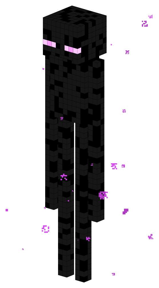
| % Enderman
% Author: IstvÃĄn SzÃĄntai (szantaii)
\documentclass{article}
\usepackage{luacode}
\usepackage{xcolor}
\usepackage{tikz}
\usepackage{tikz-3dplot}
\usepackage[active, tightpage]{preview}
\PreviewEnvironment{tikzpicture}
\setlength{\PreviewBorder}{1cm}
\definecolor{endermanblack}{HTML}{000000}
\definecolor{endermangray}{HTML}{161616}
%\definecolor{endermanpurple}{HTML}{CC00FA}
%\definecolor{endermanlightpurple}{HTML}{E079FA}
\definecolor{endermanpurple}{HTML}{FF9EFF}
\definecolor{endermanlightpurple}{HTML}{FFC9FF}
\definecolor{particlecolor}{HTML}{DF4AF8}
\begin{luacode*}
function draw_coordinate_system()
tex.sprint("\\draw[white!50!gray,thick,->] (0,0,0) -- " ..
"(3,0,0) node[text=white!50!gray,anchor=north east]{$x$};")
tex.sprint("\\draw[white!50!gray,thick,->] (0,0,0) -- " ..
"(0,3,0) node[text=white!50!gray,anchor=west]{$y$};")
tex.sprint("\\draw[white!50!gray,thick,->] (0,0,0) -- " ..
"(0,0,3) node[text=white!50!gray,anchor=south]{$z$};")
end
function tikzcube(x, y, z, color)
--[[
\draw[fill=red] (0.5, 0.5, -0.5) -- (-0.5, 0.5, -0.5) -- (-0.5, -0.5, -0.5) -- (0.5, -0.5, -0.5) -- cycle;
\draw[fill=red] (-0.5, 0.5, -0.5) -- (-0.5, 0.5, 0.5) -- (-0.5, -0.5, 0.5) -- (-0.5, -0.5, -0.5) -- cycle;
\draw[fill=red] (-0.5, -0.5, -0.5) -- (0.5, -0.5, -0.5) -- (0.5, -0.5, 0.5) -- (-0.5, -0.5, 0.5) -- cycle;
\draw[fill=red] (0.5, 0.5, -0.5) -- (-0.5, 0.5, -0.5) -- (-0.5, 0.5, 0.5) -- (0.5, 0.5, 0.5) -- cycle;
\draw[fill=red] (0.5, -0.5, -0.5) -- (0.5, 0.5, -0.5) -- (0.5, 0.5, 0.5) -- (0.5, -0.5, 0.5) -- cycle;
\draw[fill=red] (0.5, 0.5, 0.5) -- (-0.5, 0.5, 0.5) -- (-0.5, -0.5, 0.5) -- (0.5, -0.5, 0.5) -- cycle;
]]
local cube = ""
cube = cube .. "\\draw[ultra thin, fill=" .. color .. "]" ..
"(0.5 + " .. x .. ", 0.5 + " .. y .. ", -0.5 + " .. z .. ") -- " ..
"(-0.5 + " .. x .. ", 0.5 + " .. y .. ", -0.5 + " .. z .. ") -- " ..
"(-0.5 + " .. x .. ", -0.5 + " .. y .. ", -0.5 + " .. z .. ") -- " ..
"(0.5 + " .. x .. ", -0.5 + " .. y .. ", -0.5 + " .. z .. ") -- cycle;"
cube = cube .. "\\draw[ultra thin, fill=" .. color .. "]" ..
"(-0.5 + " .. x .. ", 0.5 + " .. y .. ", -0.5 + " .. z .. ") -- " ..
"(-0.5 + " .. x .. ", 0.5 + " .. y .. ", 0.5 + " .. z .. ") -- " ..
"(-0.5 + " .. x .. ", -0.5 + " .. y .. ", 0.5 + " .. z .. ") -- " ..
"(-0.5 + " .. x .. ", -0.5 + " .. y .. ", -0.5 + " .. z .. ") -- cycle;"
cube = cube .. "\\draw[ultra thin, fill=" .. color .. "]" ..
"(-0.5 + " .. x .. ", -0.5 + " .. y .. ", -0.5 + " .. z .. ") -- " ..
"(0.5 + " .. x .. ", -0.5 + " .. y .. ", -0.5 + " .. z .. ") -- " ..
"(0.5 + " .. x .. ", -0.5 + " .. y .. ", 0.5 + " .. z .. ") -- " ..
"(-0.5 + " .. x .. ", -0.5 + " .. y .. ", 0.5 + " .. z .. ") -- cycle;"
cube = cube .. "\\draw[ultra thin, fill=" .. color .. "]" ..
"(0.5 + " .. x .. ", 0.5 + " .. y .. ", -0.5 + " .. z .. ") -- " ..
"(-0.5 + " .. x .. ", 0.5 + " .. y .. ", -0.5 + " .. z .. ") -- " ..
"(-0.5 + " .. x .. ", 0.5 + " .. y .. ", 0.5 + " .. z .. ") -- " ..
"(0.5 + " .. x .. ", 0.5 + " .. y .. ", 0.5 + " .. z .. ") -- cycle;"
cube = cube .. "\\draw[ultra thin, fill=" .. color .. "]" ..
"(0.5 + " .. x .. ", -0.5 + " .. y .. ", -0.5 + " .. z .. ") -- " ..
"(0.5 + " .. x .. ", 0.5 + " .. y .. ", -0.5 + " .. z .. ") -- " ..
"(0.5 + " .. x .. ", 0.5 + " .. y .. ", 0.5 + " .. z .. ") -- " ..
"(0.5 + " .. x .. ", -0.5 + " .. y .. ", 0.5 + " .. z .. ") -- cycle;"
cube = cube .. "\\draw[ultra thin, fill=" .. color .. "]" ..
"(0.5 + " .. x .. ", 0.5 + " .. y .. ", 0.5 + " .. z .. ") -- " ..
"(-0.5 + " .. x .. ", 0.5 + " .. y .. ", 0.5 + " .. z .. ") -- " ..
"(-0.5 + " .. x .. ", -0.5 + " .. y .. ", 0.5 + " .. z .. ") -- " ..
"(0.5 + " .. x .. ", -0.5 + " .. y .. ", 0.5 + " .. z .. ") -- cycle;"
tex.sprint(cube)
end
function draw_head(x_pos, y_pos, z_pos)
local color
for x = x_pos, x_pos + 7, 1 do
for y = y_pos, y_pos + 7, 1 do
for z = z_pos, z_pos + 6, 1 do
if (x == x_pos or x == x_pos + 7 or
y == y_pos or y == y_pos + 7 or
z == z_pos or z == z_pos + 6) and
not (x == x_pos + 7 and y > y_pos and y < y_pos + 7 and z == z_pos) then
if x == x_pos + 7 and
(y == y_pos or y == y_pos + 2 or
y == y_pos + 5 or y == y_pos + 7) and
z == z_pos + 2 then
tikzcube(x, y, z, "endermanlightpurple")
elseif x == x_pos + 7 and
(y == y_pos + 1 or y == y_pos + 6) and
z == z_pos + 2 then
tikzcube(x, y, z, "endermanpurple")
else
if math.random(0, 8) < 6 then
color = "endermangray"
else
color = "endermanblack"
end
tikzcube(x, y, z, color)
end
end
end
end
end
end
function draw_bodypart(x_pos, y_pos, z_pos, x_length, y_length, z_length)
local color
for x = x_pos, x_pos + x_length - 1, 1 do
for y = y_pos, y_pos + y_length - 1, 1 do
for z = z_pos, z_pos + z_length - 1, 1 do
if x == x_pos or x == x_pos + x_length - 1 or
y == y_pos or y == y_pos + y_length - 1 or
z == z_pos or z == z_pos + z_length - 1 then
if math.random(0, 8) < 6 then
color = "endermangray"
else
color = "endermanblack"
end
tikzcube(x, y, z, color)
end
end
end
end
end
function draw_particles(x_min, x_max, y_min, y_max, z_min, z_max)
local x
local y
local z
local black_amount
local particle_size
local particle_scale
local particle_count = math.random(30, 40)
local particle
for i = 1, particle_count, 1 do
x = math.random(x_min, x_max)
y = math.random(y_min, y_max)
z = math.random(z_min, z_max)
particle_size = math.random(1, 8)
particle_scale = math.random(20, 100) / 100
black_amount = math.random(0, 25)
tex.sprint("\\tdplottransformmainscreen{" .. x .. "}{" .. y .. "}{" .. z .. "}")
for i = 0, particle_size - 1, 1 do
for j = 0, particle_size - 1, 1 do
if math.random(0, 1) == 0 and
((i ~= 0 and j ~= 0) and
(i ~= particle_size - 1 and j ~= 0) and
(j ~= particle_size - 1 and i ~= 0) and
(i ~= particle_size - 1 and j ~= particle_size - 1)) then
particle = "\\filldraw[black!" .. black_amount ..
"!particlecolor, tdplot_screen_coords] (" ..
i * particle_scale * 0.25 .. "+\\tdplotresx, " ..
j * particle_scale * 0.25 .. "+\\tdplotresy) " ..
"rectangle +(" .. particle_scale .. "*0.25, " ..
particle_scale .. "*0.25);"
tex.sprint(particle)
end
end
end
end
end
function draw_enderman(x_rotation, z_rotation)
tex.sprint("\\tdplotsetmaincoords{" .. x_rotation .. "}{" .. z_rotation .. "}")
tex.sprint("\\begin{tikzpicture}[tdplot_main_coords]")
math.randomseed(os.time())
draw_bodypart(3, -2, -30, 2, 2, 30) -- right arm
draw_bodypart(3, 1, -42, 2, 2, 30) -- right leg
draw_bodypart(3, 5, -42, 2, 2, 30) -- left leg
draw_bodypart(2, 0, -12, 4, 8, 12) -- body
draw_bodypart(3, 8, -30, 2, 2, 30)-- left arm
draw_head(0, 0, 0) -- head
draw_particles(-10, 10, -10, 10, -44, 10)
-- draw_coordinate_system()
tex.sprint("\\end{tikzpicture}")
end
\end{luacode*}
\begin{document}
\luadirect{draw_enderman(70, 130)}
\end{document} |


